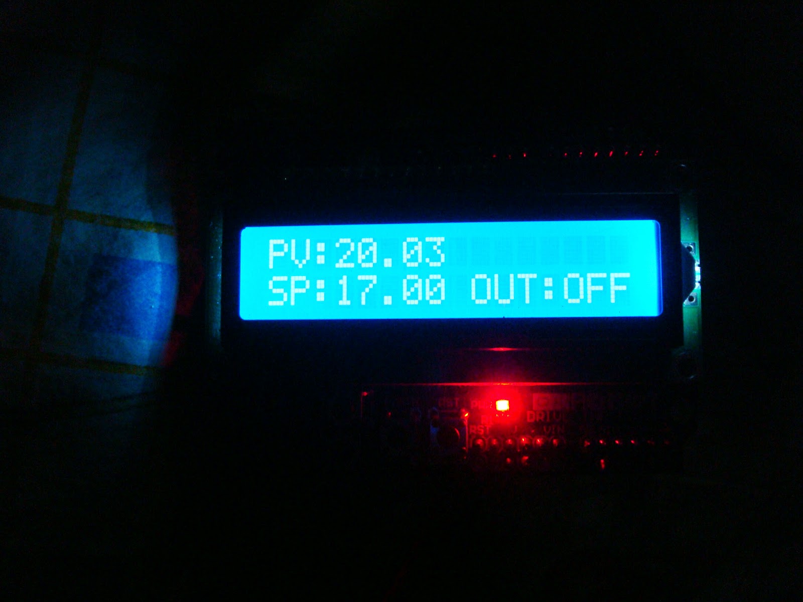
Closed loop temperature control for three-phase heater industry.
Sensor: RTD PT100 "Resistance change in temperature linear function.
Conditioner: Not over yet, for now is a voltage divider, is best to use op-amps to improve zero stability.
Control: Arduino Mega 2560.
Output Interface: Interface with power solid state relay supports 400VCA - 90A per phase, modulating the current with very stable PWM.
Actuator: For testing I use a "temperature gun" with regulated PWM solid state relay will be the real tubular resistors.
HMI or SCADA: isn´t a hmi or scada but, fulfills the function for monitoring, KST and RealTerm under windows work fine, but under ubuntu i use GtkTerm.
Other monitors can be used, scadabr or another also have to test the OPC driver for arduino but it only works on Windows and turns your Arduino into a Modbus device other option is proccessing and android.
Things to improve
Measure the temperature with two RTD averaging and improve stability condition with op-amp to improve on precision but with the ADC of arduino works great to add a function to interrupt, and cut high temperature thermocouple, to measure the power consumption of this would be great for know all consumption per phase and take decicions on failure, improve the graphics a SHIELD LCD PWM is a very well-armed great library but can be improved with a RNA or Perceptron learning of values for PID autotuning and use a slightly more powerful SCADA
Code on github for the heater.
- Regards :)
************************************************** *******************************
Update 18/05/2014
This is an update of my project control by arduino or openhardware temeperature control under PT100.
I use a mega, Freaduino 2560 or can run other arduino.
The first test showed his running its power, flexibility and the proper firmware runs on a mega one or another clone or our own microcontroller.
The downside of this project is safety pin or put wire welding isn´t very safe and meet safety regulations and standards, so the following is to improve the safety, I have seen boards that serve no intrinsic safety and function and are installed in industrial processes (Argentina :)).
Next, mount it in a Junction box "APE" on a DIN rail with sockets, DC-DC power stable and sometime make my graphic program to program ladder.
Information:
++ very good in Spanish ++
Controllino
In so many will arise, which encourages me to continue with my project of course this is an improvement but thanks to 3D printers, I'll be able to make the brackets for DIN rail housings platelets.
It occurred to me the idea of mounting on the DIN rail mega thereupon told'll print my 3D printer models have to do in OpenSCAD and a good bum looking at Thingiverse already had thought lol
Mr. jean claude ingenious make this model in OpenSCAD or other, fabulous program you download the STL model and print directly to your printer 3d.
by JEAN CLAUDE
This type of boxes or junction box gives us security against moisture and outdoor "intemperie hazardous area" house burned would contain short.
The DIN rail is a standard 35mm rail for mounting electrical applications.

Well first and foremost we mount on DIN rail with brackets, I got one but I plan to print with my i3 Prussa with the ABS housing and industrial terminal blocks using standardized.
It should be something like this is the idea.

1- Ape aluminum box
2- Standardized DIN rail
3- Industrial terminal blocks
4- DC-DC power filters
5- Grounded - Fuses.
Hardware:
Enclosure: IP66 JunctionBox
Sensor: PT100 double with two three-wire RTD.
Controller: Freaduino mega 2560.
Display: LCD 16x2 is a shield but I will make an extension with terminal blocks.
Power Interface: Solid state relay 400Vac and 90A of .
Software:
Among the improvements calibration was performed with a dry thermal bath contrasted with a thermometer Thermocouple fluke 51 k, and a pyrometer Raytek for safety, use a double PT100 fault if some have their backup works with either and is a priority, if they fail both the DIP process stops and go without alarming the same function.
You can increase or decrease the required setpoint from keypads.
According configure and works with both declare arduino mega as the one.


With respect to security wiring board and I plan to use a shield of this type but I think I will myself to realize the plate here in Argentina isn´t got no one to one but I'm not convinced.

Regards ...
Update 30/05/2014 ******************************************** *************
Well so it is becoming a little better and not look like a tangle of cables "It is dedicated to the person who told me it was a tangle of wires "¬¬ hahaha


It gets better :)
********************************************************************************************************
Update 20/11/2014
I found myself with the drawback of using terminal blocks give more security to the board did not find the screw shield in Argentina so assemble your own and after several models fritzing mountain all on one plate so I'll take more verbose but future I want to mount on a DIN rail :)


Regards.

No hay comentarios.:
Publicar un comentario