jueves, 20 de noviembre de 2014

Arduino - GPS EM406 Bluetooth Acelerometro MMA6671

Bueno aca presento mi pequeño proyecto de GPS con conexion  Bluetooth y acelerometro...

Lista de materiales
Arduino uno o micro similar

Modulo Serie Bluetooth
Datasheet: http://www.exp-tech.de/service/datasheet/HC-Serial-Bluetooth-Products.pdf 


Version para 3.3vcc


Version para 5vcc


Las dos son las mismas nada mas que el segundo shield posee pines y reguladores de tension, led, etc.

Modulo Serie GPS EM406
Datasheet: https://www.sparkfun.com/datasheets/GPS/EM-406A_User_Manual.PDF


Video demo de su funcionamiento.....


Sldos...

Arduino - RTD PT-100 PID PWM (English version)


Closed loop temperature control for three-phase heater industry.

Sensor: RTD PT100  "Resistance change in temperature linear function.

Conditioner: Not over yet, for now is a voltage divider, is best to use op-amps to improve zero stability.

Control: Arduino Mega 2560.

Output Interface: Interface with power solid state relay supports 400VCA - 90A per phase, modulating the current with very stable PWM.

Actuator: For testing I use a "temperature gun" with regulated PWM solid state relay will be the real tubular resistors.

HMI or SCADA: isn´t a hmi or scada but, fulfills the function for monitoring, KST and RealTerm under windows work fine, but under ubuntu i use GtkTerm.
Other monitors can be used, scadabr or another also have to test the OPC driver for arduino but it only works on Windows and turns your Arduino into a Modbus device other option is proccessing and android.

Things to improve
Measure the temperature with two RTD averaging and improve stability condition with op-amp to improve on precision but with the ADC of arduino works great to add a function to interrupt, and cut high temperature thermocouple, to measure the power consumption of this would be great for know all consumption per phase and take decicions on failure, improve the graphics a SHIELD LCD PWM is a very well-armed great library but can be improved with a RNA or Perceptron learning of values ​​for PID autotuning and use a slightly more powerful SCADA


Code on github for the heater.

  • Regards :)


************************************************** *******************************
Update 18/05/2014

This is an update of my project control by arduino or openhardware temeperature control under PT100.
I use a mega, Freaduino 2560 or can run other arduino.
The first test showed his running its power, flexibility and the proper firmware runs on a mega one or another clone or our own microcontroller.
The downside of this project is safety pin or put wire welding isn´t very safe and meet safety regulations and standards, so the following is to improve the safety, I have seen boards that serve no intrinsic safety and function and are installed in industrial processes (Argentina :)).
Next, mount it in a  Junction box "APE" on a DIN rail with sockets, DC-DC power stable and sometime make my graphic program to program ladder.

Information:
++ very good in Spanish   ++

Controllino

In so many will arise, which encourages me to continue with my project of course this is an improvement but thanks to 3D printers, I'll be able to make the brackets for DIN rail housings platelets.

It occurred to me the idea of mounting on the DIN rail mega thereupon told'll print my 3D printer models have to do in OpenSCAD and a good bum looking at Thingiverse already had thought lol

Mr. jean claude ingenious make this model in OpenSCAD or other, fabulous program you download the STL model and print directly to your printer 3d.

by JEAN CLAUDE


This type of boxes or junction box gives us security against moisture and outdoor "intemperie hazardous area"  house burned would contain short.


The DIN rail is a standard 35mm rail for mounting electrical applications.


Well first and foremost we mount on DIN rail with brackets, I got one but I plan to print with my i3 Prussa with the ABS housing and industrial terminal blocks using standardized.
It should be something like this is the idea.


1- Ape aluminum box
2- Standardized DIN rail
3- Industrial terminal blocks
4- DC-DC power filters
5- Grounded - Fuses.


Hardware:

Enclosure: IP66 JunctionBox
Sensor: PT100 double with two three-wire RTD.
Controller: Freaduino mega 2560.
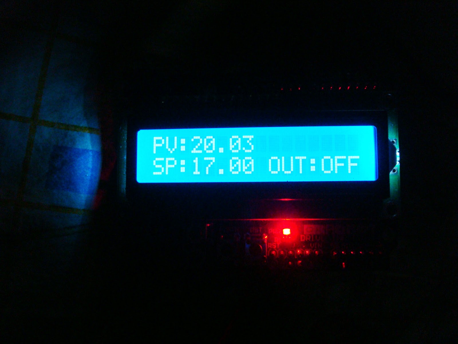
Display: LCD 16x2 is a shield but I will make an extension with terminal blocks.
Power Interface: Solid state relay 400Vac and 90A of .

Software:


Among the improvements calibration was performed with a dry thermal bath contrasted with a thermometer Thermocouple fluke 51 k, and a pyrometer Raytek for safety, use a double PT100 fault if some have their backup works with either and is a priority, if they fail both the DIP process stops and go without alarming the same function.
You can increase or decrease the required setpoint from keypads.

According configure and works with both declare arduino mega as the one.


With respect to security wiring board and I plan to use a shield of this type but I think I will myself to realize the plate here in Argentina isn´t got no one to one but I'm not convinced.


Regards ...

Update 30/05/2014 ******************************************** *************

Well so it is becoming a little better and not look like a tangle of cables "It is dedicated to the person who told me   it was a tangle of wires "¬¬   hahaha


It gets better :)

********************************************************************************************************

Update 20/11/2014

 I found myself with the drawback of using terminal blocks give more security to the board did not find the screw shield in Argentina so assemble your own and after several models fritzing mountain all on one plate so I'll take more verbose but future I want to mount on a DIN rail :)


Regards.

martes, 18 de noviembre de 2014

Arduino - Nodo souliss para domotica

Arrancando con mi proyecto de domotica me encontre con una app para android muy buena facil de configurar y funciona en mi celular y tablet es una app italiana muy interesante ya la portaron al español.

De aca bajas tanto la app para android como el firmware para arduino(conjunto de librerias y ejemplos)


Las funciones y logica me parece muy buena esta orientada a programacion de PLC manejo de dispositivos, slots, timing etc.
Otra cosa que me sorprendio es la comunicacion el cual es peer to peer o todos a todos por cualquier medio ehternet - Wifi - RF- RS485 - RS232 a traves de vNET o virtual NET en donde por un canal pueden haber varios tipos de comunicacion.


Pruebas de hardware y consumos 2 shield de 8 reles.


Probando todos los reles desde arduino con un par de bucles del tipo

i=pin_inicial;
for(i=0<pin_inal;i++)
{
pinMode(i,OUTPUT);
digitalWrite(i,LOW); //logica invertida
}


Todos consumen alrededor de 1.3A casi 90mA por rele la temperatura es infernal si estan todos activos como precaucion y pensando en maxima carga si o si colocar un fan o peltier para refrigeracion y problema solucionado.


Proyecto para gabinet domotica.

Alimentacion 220vca de back-up
*************************
Rectificador 220vca a 24vcc (cargando mientras hay tension por algun corte activa el inversor)
Regulador y control de carga a baterias 12vcc (un banco de dos baterias 12vcc)
Inversor de 12vcc a 220vca - 1500watt
(la electronica no consume tanto estaba pensando en una fuente con 24vcc/12vcc(motores ) - 5vcc -3.3vcc)

Gateway
************
router d-link (1 WAN - 4 LAN - 1 WLAN)

ServerNAS
*************
Rasperry PI B 512MB(conexion escritorio y shell remoto)
Disco USB 500GB
Placa de red LAN - WLAN

nodo 1 (como prueba no esta definitivamente armado)
*********
1 - fuente 5vcc - 3.3vcc
1 - arduino mega 2560(souliss lib)
2 - modulos de salidas 8 Reles
1 - placa enc28j60

Control Modo remoto
*************************
Celular samsung galaxy chat - soulissApp
Tablet generica - soulisApp

La primer prueba espectacular es increible me dio un poco de problemas el mega con respecto a los pines pero mirando codigo me di cuenta por si le sirve a alguien...

enc28j60 -> Arduino Mega 2560 definido en spi.h
CS --> D10 (creia era el 53 y nooo)
SI     ->   D51
SO     --> D50
SCK --> D52

souliss/framevNet/drivers/ethENC28J60/spi.h
define atmega 2560
BIT4 --->0x10 - 00100000
DDRB -->portB como salida
PORTB-->lo pone en alto

segun el pinout del atmega se podria cambiar para ocupar el pin 53 pero no lo hice lo pase al D10 y fue


PB7 PB6 PB5 PB4 PB3 PB2 PB1 PB0
0 0 0 1 0 0 0 0 --->PB4 pin 10 del mega 0x10
0 0 0 0 0 0 0 1 ---->PB0 pin 53 del mega 0x1 (pero no lo probe)

Programa soulissAPP corriendo desde tablet generica. (16 dispositivos o slots)


me quedan hacer un par de montajes para que no quede todo suelto agregar pulsadores o comando de vos un gabinete y tomas corriente para rack por ahora.


Sldoss...


**********************Actualizacion   03/12/14**********************************
Bueno despues de hacer funcionar todo como corresponde se me ocurrio armar un rack de comunicaciones u algo parecido siempre tuve ganas de tener un rack y como tenemos equipo de comunicacion controladores rele con tensiones y alimentaciones me parece ideal, la idea seria que quedara algo asi los que puedan  armar el cableado de cero desde el rack a los cañeros o usar tomacorrientes por RF en mi caso voy a conectar los dispositivos hasta los toma corrientes del rack :) me gusta mas asi quizas hasta bandeja utilize como se utiliza en la industria :) u oficinas con falsos pisos esto es poco comun en hogares normales pero como no soy muy normal que digamos lo voy a pensar.


Por ahora solo armaria un rack para mantener todo ordenado los dispositivos que conecte los puedo pasar por cable canal pasarlos por los cañeros ya veremos o usar tomas RF.

La idea es armar un gabinete rackeable la fuente quiza la separe de tener espacio por el ruido electromagnetico.

1  - rack con la fuente el arduino y los reles (no definido aun)
2  - rack con el router wifi en modo bridge (WDS) o sea replicando el principal si se cae el principal entras por  el bridge :) probado y funciona :)
3  - rack con tomacorrientes de 20A para alimentacion de fuentes y equipo de comunicacion
4  - rack de tomacorrientes de salida (1 x 8 20A) para los dispositivos 1 al 8
5  - rack de tomacorrientes de salida (2 x 8 20A) para los dispositivos 9 al 16


Sldos espero les guste....

 lo anoto ya o me olvido

Estaria bueno no solo habilitar el dispositivo sino tb controlarlo

esto me gusto emular controles remotos(tv-home-dvd-aire-decoder-etc)
http://www.ladyada.net/wiki/tutorials/learn/sensors/ir.html 


esto tb me interesa emular mandos rf aunque lo del roling code suena complicado de replicar
http://en.wikipedia.org/wiki/Rolling_code


Sldos..

Que alegría un compañero que trabaja en comunicaciones,  me regalo un rack estaba desarmado lo arme y ya parece un rack de comunicaciones es solo prueba aun le falta banda


 Sldos...

***************************09/12/14**********************************************
Bueno tras tatar de montar las placas para que queden prolijas para armar los tomacorrientes asi va quedando no me convence del todo aun en cuanto a prolijidad ni orden de cables....


por un lado tengo
La fuente de 220vca a 12 - 5 y 3.3vcc
La placa arduino - enc28j60
La interface de reles 16 reles para 220vca
El fan de 12vcc
y el router en modo bridge WDS

dejare en el frente conexiones de red y entrada al arduino para configuraciones y salidas alimentaciones por la parte posterior.


Funciona corectamente pero no me cierra el orden aun.

Sldos..


********************************16/12/14******************************

bueno va mejorando el orden y el cableado


Sldos...


Actualizacion  18-02-2015

Mejoras en cableado, borneras, y tomas para rack mas modulo HC-05 para poder programarlo de manera inalambrica.


Modulo Bluetooth HC-05 (Programacion inalambrica por bluetooth)


Cableado de reles protecciones y borneras.


Tomas para rack 19"


Sldos...